Luff at back or Side of mast? Aug 13
1.0 What is in this article?
Ever since Manfred Curry wrote his pioneering book, the idea has been around that by having the mainsail luff on the lee side of the mast you would get a better flow over the lee side of the sail and hence a more efficient sail. This article explores this idea. There are three parts:
• The first looks at the flow round both central and lee sided positions and discusses other differences.
• The second describes some wind tunnel tests and the results obtained.
• The third one looks at why the results came about.
• The last is a comment on practicality.
2.0 Flow patterns and other matters
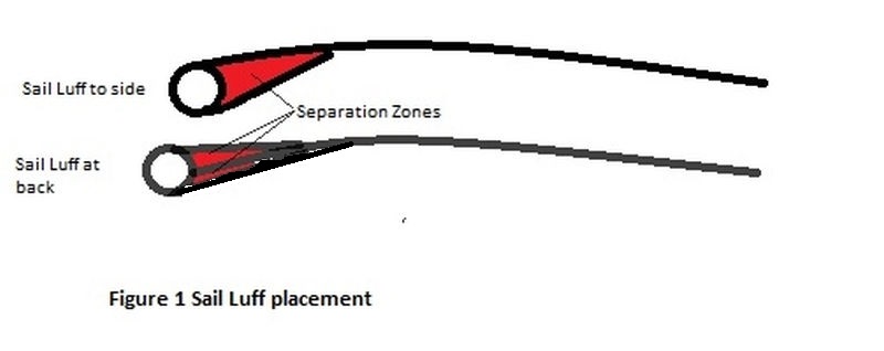
When the wind blows over the sail, the mast creates a separation zone immediately behind it. With the luff of the sail taken to the lee side, this separation zone fills in the unevenness on the windward side. If the sail luff is fastened to the centreline of the mast (e.g. in a luff groove or with a taut jackstay) then separation zones occur both on the leeward and windward sides of the sail near the luff. The relative efficiency depends on which separation arrangement uses up the least energy and hence has the lower drag. This cannot be seen, so it needs be examined by measuring lift and drag.
There are a few other things that happen.
Firstly, the wind does not see the mast and sail as separate items but as a combined item. Thus it sees the chord (width) of the mast/sail as extending from the front of the mast to the leech of the sail. Now with the luff on the lee side of the mast the aerodynamic chord of the sail is reduced by half the mast diameter as compared to having the luff on the mast centreline because the sail overlaps the mast by this much.
Secondly, with the sail on the lee side of the mast, the actual camber is increased a bit due to the mast diameter but decreased to some extent because the luff is fixed behind the mast at head and tack so that when the centre of the luff slides round the side, the effect of any luff round in the sail is negated and the sail becomes flatter. The net result of these two opposite effects will vary depending on the individual sail and mast.
3.0 Wind Tunnel Tests
Some years ago four of us from the NS14 Class hired the wind tunnel at the University of Sydney for a day. Frank Bethwaite (Test pilot and designer of the Laser 2 and Tasar), Dr Pat Smith (CSIRO scientist), Charlie Mansfield (Manager and Mechanical Engineer) and me, (Civil Engineer) made up the team. The primary objective was to try out various over-rotating and conventional mast configurations. Among the tests were two that had round masts. The configurations are shown in Figure 2. 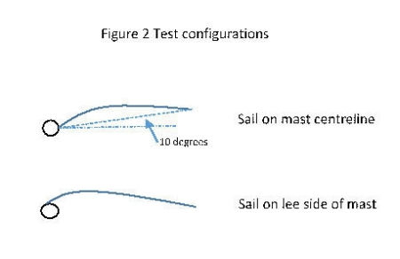
With a fixed mast, the boom is usually out to leeward of the centreline and at the midpoint of the sail, the twist in the sail moves the sail leech further out again. To allow for this, in the tests with the luff of the sail on the centreline, the sail was taken back 10 degrees to simulate this as shown in the top diagram in Figure 2.
The masts were both 1.25 inches diameter and the chord of the cloth was 24 inches, making the ratio of mast diameter to chord 0.052. By comparison this same ratio for the mid height of an IOM A or B rig mainsail is 0.47 which is very close to the same.
In both tests the camber was 1.6 inches or 6.7% which is a little less than usual for an IOM, still this is all close enough to be relevant.
The tests were done at Reynold’s Numbers of 400,000. This is higher than would be expected for an IOM rig where the A rig works up to a Reynolds Number of about 70,000, however the lift and drag coefficients are in the same ballpark as those obtained at Southampton and reported by Lester Gilbert, so it is likely that the results apply to IOMs and other radio yachts.
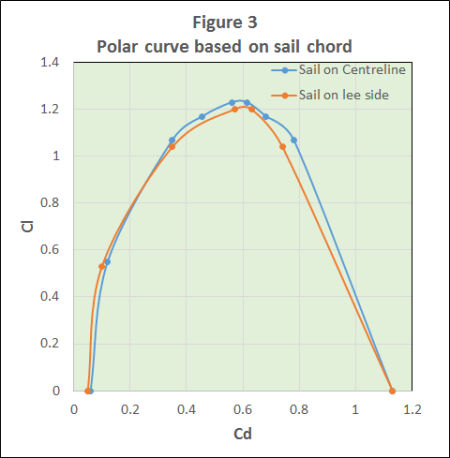 Figure 3 shows the results in the usual polar diagram with the drag coefficient on the horizontal axis and the lift coefficient on the vertical one. For this presentation the chord for calculating the coefficient was taken as that of the cloth. This is normal given that most class rules measure the mast and sail separately and do not allow any extra because the luff is overlapping the mast. It will be seen that the sail on the centreline is equal or superior everywhere except when the sail is operating at very low lift coefficients (i.e. luffing closer to the wind but not flapping), and even then the difference is close to the accuracy of the tests.
4.0 What causes these effects?
To investigate whether this is because the sail on the mast centreline is inherently more efficient or whether it gives better results because the (sail + mast) chord is larger, the results were reworked using the actual aerodynamic chord to calculate the lift and drag coefficients. The results are in Figure 4.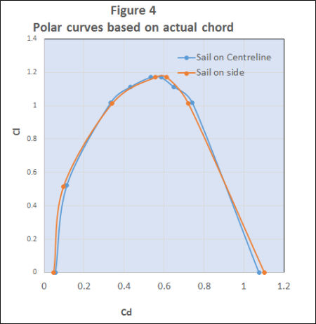
It will be seen that using this method the results are very similar for the two configurations. The apparent superiority of the lee placed luff at low lift coefficients remains, though still close to the accuracy of the tests and not conclusive. It would seem that a reasonable conclusion from all this is that leeward placement of the sail luff on the mast does not confer any significant increase or decrease in efficiency but that the loss of aerodynamic chord means that one is better off with the luff on the centreline.
5.0 Some practical stuff
There are some other things from this: if on a model yacht you use a non-rotating mast with a luff groove or a jackstay that does not move around the mast with the boom, efficiency will be compromised off the wind because the sail luff will then come off the windward side of the mast which is generally acknowledged to be undesirable.
Getting over this is not easy. The obvious way is to have the mast rotate, but that is difficult given the nature of the rules on rigging for an IOM, namely the presence of the spreaders. If a jackstay is taken to the head attachment point on the swivelling support at the mast head that is OK for the upper part of the sail but arranging for the jackstay to rotate about the mast at the bottom is almost impossible given the IOM rules about the pivot point of the gooseneck. Given the narrow band of angle of attack where this would pay off makes it arguable whether the complexity and weight of any arrangement for this would be worth it.
Colin Thorne Aug 2013